 | –≠–ª–µ–∫—Ç—Ä–æ–Ω–Ω—ã–π –∫–æ–º–ø–æ–Ω–µ–Ω—Ç: AN7289 | –°–∫–∞—á–∞—Ç—å:  PDF PDF  ZIP ZIP |
ICs for FM/AM Tuner
1
AN7289NSC
FM-FE
+
AM IC for car radio
s
Overview
The AN7289NSC is an IC having FM-FE
+
AM
functions for car radio. A tuner block of car radio
can be constructed by combination of this IC and
the AN7293NSC / NFBQ.
s
Features
∑
A less number of electrolytic capacitors is required
(3 capacitors reduction compared with our con-
ventional IC)
∑
AM: Practical sensitivity is improved by 2 dB by
ATC
∑
AM: Strong input characteristics is improved by
2-loop AGC function
s
Applications
∑
Car radios
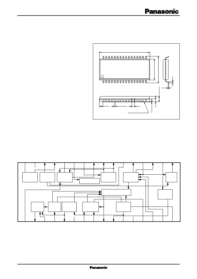
SSOP032-P-0375
Unit: mm
1
2
3
4
5
6
7
8
9
10
11
12
13
14
15
16
V
CC
GND1
32
31
30
29
28
27
26
25
24
23
22
21
20
19
18
17
GND2
FE
OSC
FM
AGC
FM/AM SW
FM
mix.
AM
mix.
AM
ATC
FM
IF-amp.
AM
RF-AGC
AM
IF-AGC
AM
IF-amp.
AM
OSC
AM.S-meter
AM
SSC
AM
det.
s
Block Diagram
17.81
±
0.3
0.35
±
0.1
7.2
±
0.3
9.3
±
0.3
2.0
±
0.2
0.1
±
0.1
32
17
1
16
0.15
0.3
1.0
1.23
0.9
Seating plane
AN7289NSC
ICs for FM/AM Tuner
2
Parameter
Symbol
Rating
Unit
Supply voltage
V
CC
9.1
V
Supply current
I
CC
56
mA
Power dissipation
*2
P
D
380.2
mW
Operating ambient temperature
*1
T
opr
-
35 to
+
80
∞
C
Storage temperature
*1
T
stg
-
55 to
+
125
∞
C
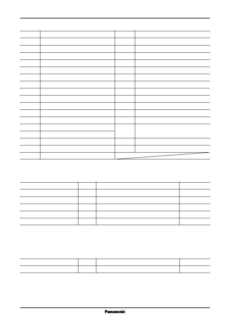
s
Pin Description
Pin No.
Description
18
FM-IF input
19
AM-RF gain control
20
AM-mix. input
21
FM-PIN-diode driver
22
AM-OSC coil pin
23
FM-mix. output (2)
24
FM-mix. output (1)
25
FM-PIN-diode driver
26
FM-mix. input
27
V
CC2
/ FM / AM SW
28
FM-AGC output
29
FM-OSC buffer output
30
AM-OSC buffer output / FE-AGC
sensitivity setting
31
GND2
32
FM-OSC coil pin
Pin No.
Description
1
FM-keyed-AGC input
2
AM-AF output / LO setting
3
AM-ATC input
4
AM-IF level detection
5
AM detection output
6
V
CC1
7
AM-IF counter output / DX / LO SW
8
AM-SD output
9
AM-signal meter output
10
FM-IF output
11
AM-IF output
12
GND1
13
SSC
14
AM-RF level detection
15
AM-WAGC detection / DX setting
16
AM-IF input
17
AM-mix. output
s
Absolute Maximum Ratings
Note) *1: Except for the power dissipation, operating ambient temperature, and storage temperature, all ratings are for T
a
=
25
∞
C.
*2: T
a
=
80
∞
C
s
Recommended Operating Range
Parameter
Symbol
Range
Unit
Supply voltage
V
CC
7.2 to 9.0
V

ICs for FM/AM Tuner
AN7289NSC
3
s
Electrical Characteristics at T
a
=
25
∞
C
1. AM mode
V
CC
=
8.0 V, f
IN
=
1 MHz
AM tuning condition: OSC output frequency
=
1 450 kHz
±
500 Hz
Parameter
Symbol
Conditions
Min
Typ
Max
Unit
AM consumption current
amI
t1
Without input
28
36
44
mA
AM-AF output
amV
O
AM-AF output at V
IN2
=
74 dB
µ
,
100
125
155
mA
400 Hz 30%
AM signal-to-noise ratio
amSN
AM-AF output S/N at V
IN2
=
74 dB
µ
,
48
52
58
dB
400 Hz 30%
AM-AGC width
amW
AM-AF output when input changes
55
59
63
dB
-
10 dB at V
IN2
=
74 dB
µ
, 400 Hz 30%
AM-ATC operation
amATC
(Output ratio [dB] of 400 Hz and
3.5
6.5
9.5
dB
3 kHz when V
IN2
=
18 dB
µ
)
-
(Output
ratio [dB] of 400 Hz and 3 kHz when
V
IN2
=
74 dB
µ
) 80% Mod., AM-AF Out
output
AM-distortion 1
amT
1
V
IN2
=
74 dB
µ
400 Hz 80%
0.01
0.5
1.5
%
AM-AF output distortion
AM-distortion 2
amT
2
V
IN2
=
130 dB
µ
400 Hz 80%
0.01
0.5
1.5
%
AM-AF output distortion
AM wide band AGC on input
amV
W
f
IN2
=
1.4 MHz Input when pin 15
97
103
109
dB
µ
voltage becomes below 3 V
AM local oscillation buffer output
amV
OS
Without input
160
210
260
mV
AM-IF count output 1
amIF
1
V
IN2
=
40 dB
µ
150
210
270
mV
AM-IF count output 2
amIF
2
Without input
10
mV
AM-SD output 1
amSD
1
V
IN2
=
40 dB
µ
4.5
4.9
5.1
V
AM-SD output 2
amSD
2
Without input
0.0
0.2
0.5
V
AM signal meter output 1
amV
S1
Without input, pin 9 voltage
1
50
200
mV
AM signal meter output 2
amV
S2
Pin 9 voltage at V
IN2
=
30 dB
µ
0.7
0.95
1.2
V
AM signal meter output 3
amV
S3
Pin 9 voltage at V
IN2
=
130 dB
µ
4.1
4.8
5.1
V
AM search sensitivity DX
amDX
AM-IF count output is 120 mV or over
24
30
36
dB
µ
V
IN2
when f becomes 450 kHz
±
2 kHz
AM search sensitivity LO
amLO
AM-IF count output is 120 mV or over
44
50
56
dB
µ
V
IN2
when f becomes 450 kHz
±
2 kHz

AN7289NSC
ICs for FM/AM Tuner
4
s
Electrical Characteristics at T
a
=
25
∞
C (continued)
2. FM mode
V
CC
=
8.0 V, f
IN1
=
98 MHz
FM tuning condition: OSC output frequency
=
108.7 MHz
±
10 kHz
Parameter
Symbol
Conditions
Min
Typ
Max
Unit
FM local oscillation buffer output
fmV
OS
f
OSC
=
108.7 MHz without input
140
200
260
mV
FM-IF output level
fmIF
V
IN1
=
71 dB
µ
50
95
140
mV
FM-AGC sensitivity
fmAGC
V
IN1
level when V
28
becomes 3 V
59
63
67
dB
µ
FM-AGC voltage (high)
fmV
aH
V
IN1
=
70 dB
µ
V
28
6.0
6.4
6.8
V
FM-AGC voltage (low)
fmV
aL
V
IN1
=
82 dB
µ
V
28
0.05
0.5
V
FM consumption current
fmI
t
Without input
26
35
44
mA
s
Application Circuit Example
1
2
3
4
5
6
7
8
9
10
11
12
13
14
15
16
AM-AF Out
AM-IF Count
FM-IF Out
5 V
AM-SD Out
AM-S.Meter
32
31
30
29
28
27
26
25
24
23
22
21
20
19
18
17
FM-AGC
FM-MIX In
FM-Pin D
AM-ANT
AM-VT
FE-VT
KEYED-AGC In
V
CC
VfOSC
VaOSC
FE
OSC
FM
AGC
FM/AM SW
FM
mix.
AM
mix.
AM
ATC
FM
IF-amp.
AM
RF-AGC
AM
IF-AGC
AM
IF-amp.
AM
OSC
AM.S-meter
AM
SSC
AM
det.